A Cheap Oscilloscope Kit - DSO150
A cheap tool for the electronics tinkerer

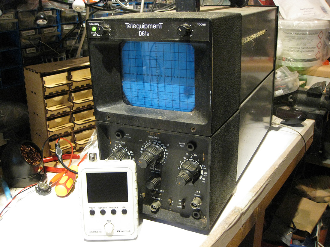
An oscilloscope is a nice to have tool for someone tinkering with electronics and properly a necessity for a serious electronics engineer. I am definitely the former - but I did at one stage acquire a traditional CRT based oscilloscope. However this is a big beast, seldom used, and lives in a cupboard in my cave. I really just don’t have the bench real estate to have it on display. Recently I have seen LCD digital scopes which are much more compact, but they have a hefty price tag.
Enter Banggood! They are selling a small lcd oscilloscope for around £16 made by JYE Tech. Here is what is was like to build.
I’ve previously ordered a component tester, which although works well came as bare, contracted boards with no case. I needed to find one on thingyverse to print. The JYE Tech scope was very different. When it arrived I was please to see it came in a nice little white box. Opening that there was a compact set of test leads, with a BNC on one end and croc clips on the other.
There were three circuits boards in the box, and these, thankfully had been pre-populated with the surface mount chips. The boards were neatly packed in anti static envelopes, and at the bottom of the box was a very well made abs case in which hid a bag of components. The box also contained two full colour, double sided sheets of instructions.
This was not like any of the kits that I have received from china previously. This is a well thought out kit with decent packaging and directions.
The instructions are in clearly marked steps with photos of the board you are working on. I would suggest that you have a good look at the photos provided as they give clues as to how to build this without mistakes. Have a look at my build video below as well if you are going to get one of these so that you don’t make the same mistakes as me, which were largely to do with deciding which side of the board to mount the components on.
Although I summarise the build on this post, you can watch me bumbling through it on the LONG video below:
Construction goes like this:
- Add the tactile switches to the main board, power it up and check that the screen works.
- Add the rest of the hardware to the main board (test terminal, BNC, power switch and headers. Remove a test surface mount resistor
- Build the rotary encoder board
- Connect encoder board to main board and attach to front panel
- Populate smaller analog board. This has some very small resistors, so I used my component tester to identify these which was easier for me than working out the colours.
- Connect the analog board to the main board, power up the board again and check the voltages at the test points against the table in the instructions.
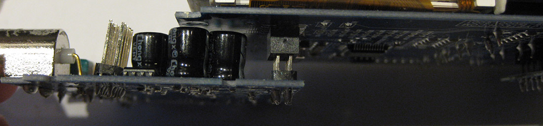
- Disconnect the analogue board from the main board and re-connect it with the lower PCB header, this gives access to the variable capacitors whilst the unit is switched on so that you can adjust them (I thought this was really well thought out - once I had realised that this was what the instructions were telling me to do.
- Once calibrated, remove the analogue board from the main board and screw the analog board to the back of the case ensuring that you hook the end panel onto the BNC and over the switch before you do.
- Connect the main and analog boards together loosely, slip over the other panel over the other end of the board, and attach the rest of the case bezel. Note that the bezel is slightly thicker at the end which goes over the lcd than at the other end of the case - and only really attaches correctly when you work this out. Screw the case together.
For your delectation, here are the mistakes I made whilst building it:
- I used the wrong screws to attach the encoder to the front panel.
 You should use the small screws to connect the board as above, saving the large ones for securing the case together.
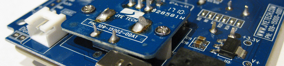
- I put the test connector on the wrong site of the main board. Then I did the same with the ‘optional’ JST power socket. Here are both on the correct side:
- One of the capacitors on the main board tested faulty on the component tester. I still installed it - and I don’t think that it has caused any problems. I'm putting this down to the component tester not being able to handle this small amount of capacitance.
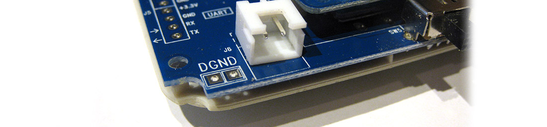
- When testing the voltages, I connected the negative of the meter to the test connector. this meant I was getting all wrong voltages, for instance 1.67 volts where I should have been getting 0v. I realised later on that I should have connected it to the digital ground test pad (DGND) on the board, not to the spade connector. You can see this below next to the white JST plug:
- I got very confused with the calibration section, until I realised that I had to look carefully at the pictures and saw that I needed to used the second connector on the analog board to attach it to the main board.
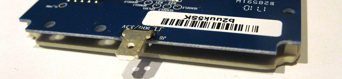
 I couldn’t find the test connector on the analog board either - In the end I realised that for calibration I had to connect the red lead to the SPADE connector:
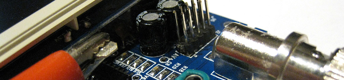
- Finally as you may have guessed from point 9 above, I couldn’t get the bezel to fit, until I realised that it only went on one way, and I had chosen the wrong one.
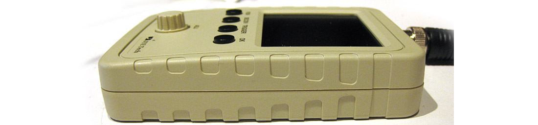
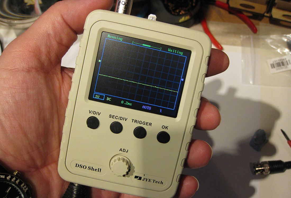
The scope looks and feels really nice once built, and feels like a small quality product. I may write about some other tinkerings with it at some point, but it seems like a very cheap addition to your tools if you are like me, tinkering with electronics.
You can buy this kit from Banggood here:
Original JYE Tech DSO-SHELL DSO150 15001K DIY Digital Oscilloscope Kit With Housing
Finally - although my old scope was a dual beam version, the DSO150 wins hands down when it comes to workbench real estate:
16-Jun-2017 Add comment
blog comments powered by Disqus Permanent Link