Electrons: LEDs, and connecting them to the Trinket
and a Cylon effect!
I love LEDs. I always have done, and still am amazed at how little power they consume.
Every time you see a LED used in a circuit it has a resistor attached to it, so I’m going to connect one with a resistor to my breadboard power rails.
Although I had a box of LEDs lying around, for this experiment I spent about £2.50 buying a “Electronic Parts Pack KIT for ARDUINO component Resistors Switch Button” on eBay which came with 3 lots of 4 different coloured LEDs, as well as some resistors and switches and other bits to add to my component collection. If you are willing to wait for these to come from Hong Kong, this is a cheap way to buy a selection of more bits for future experiments. You could also buy around 100 LEDs for 99p, and about 200 resistors for 99p too. So this stuff is cheap,
So to wire in a LED I just plug the long lead of the LED into the positive rail, the short lead into the a centre row, and connect that row back to ground, negative with the resistor. Simple and it should light up.

The resistor stops too much power going to the LED - which will use all the power it gets, go very bright, and ping into non-existance without the resistor. There are calculations you can do to work out the resistor value based on the voltage - but I just put one in there and see if its bright enough.
One tip though - if you have a LED where the leads have been snipped - keep a 3v coin cell (like a CR2032) around and you can easily use that to test the led polarity - and you don't need a resistor when you use this type of cell.

The final thing that I should do is put a switch in - but that's a bit trivial - you have created your own switch as you insert, or remove your resistor, but now we can wire up an LED all that remains is to connect some to the trinket.

If you look really closely you’ll see that the trinket has some pins marked #0-#4 so we can use one of these pins as a route to earth, in other words a switch! to control an external LED with its resistor.
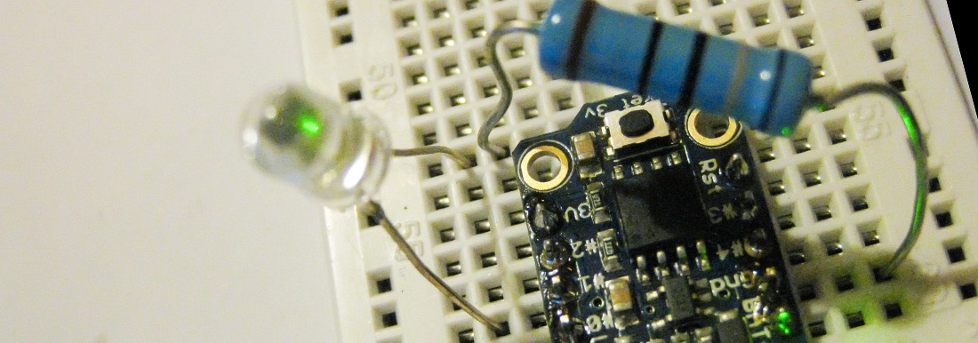
The first test will be to wire up an external LED to the digital 1 pin, which is the same control which flashes the on board LED. If we wire that up we can use the blink program to blink both the internal and external LEDs at the same time.
Here's how I connected it:

This puts the long wire of the LED into pin 1, then connect the other LED to the resistor, and that to ground. This makes the External LED flash with the on board one.
An interesting thing happens though when I connect the LED directly to power, and then the other lead through the Resister to pin 1. This makes the external LED come on when the internal one is off, and vice versa. You can do that with an external LED too, which is wired like this approximately:

So depending on how you wire the LED (in the power to the pin, or on the way from the pin to ground), you can use a pin to turn it on (when the pin is HIGH), or turn it off (when the pin is HIGH).
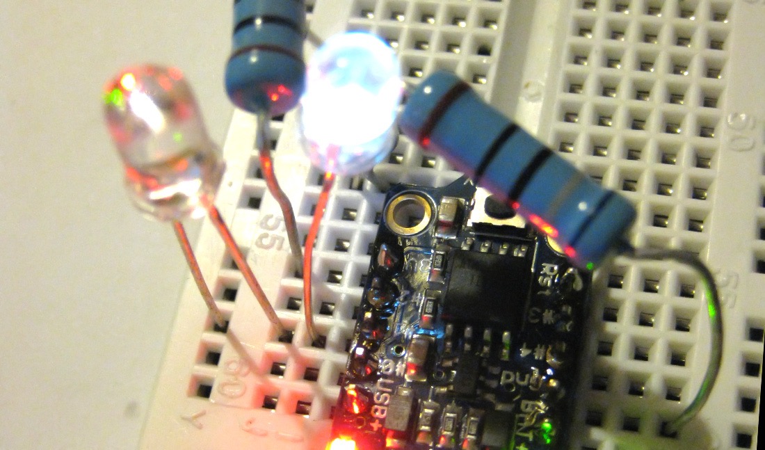
So now all that remains is add an LED to each of the output pins, and write a program to flash them.
Here is a completed setup showing my cylon effect - which moves the lit LED back and forth in a familiar way.
And here is the modified blink programme which controls 4 LEDs as opposed to just the one:
/*   Blink
   taken over by the cylons (or Kitt)
   */
   int led = 1;
   // blink 'digital' pin 1 - AKA the built in red LED
   // the setup routine runs once when you press reset:
   void setup() {
     // initialize the digital pin as an output.
     pinMode(led, OUTPUT);
     pinMode(2, OUTPUT);
     pinMode(3, OUTPUT);
     pinMode(4, OUTPUT);
     }

     void loop() {
     digitalWrite(led, HIGH);
     delay(100);
     digitalWrite(led, LOW);
     digitalWrite(2, HIGH);
     delay(100);
     digitalWrite(2, LOW);
     digitalWrite(4, HIGH);
     delay(100);
     digitalWrite(4, LOW);
     digitalWrite(3, HIGH);
     delay(100);
     digitalWrite(3, LOW);
     digitalWrite(4, HIGH);
     delay(100);
     digitalWrite(4, LOW);
     digitalWrite(2, HIGH);
     delay(100);
     digitalWrite(2, LOW);
     }
30-Nov-2014 Add comment
blog comments powered by Disqus Permanent Link