Building a RichRap 3dr - Part 3 - Assembling the frame
Now its beginning to look like it should
The next job was getting the extrusion into the printed part - what I hadn't realised was that the parts tend to have a slight lip on the first layer - this made fitting the extrusion into the part problematic. In the end I used a emery board to give the hole a slight outward chamfer, then the extrusion fitted in perfectly. I'll learn to do this in my clean up from now on.
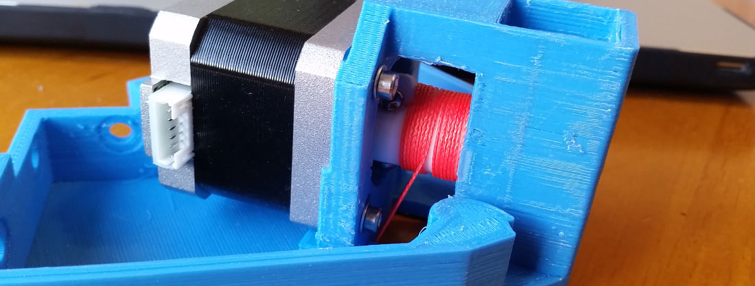
My next worry was cutting the wires that connect to the control board. I was unsure if I ought to do this - but had little choice unless I wanted to run the wires on the outside of the extrusion. So I cut off the plugs about 2 inches away from the board socket - and I'll need to re-connect these again later on.
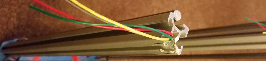
So now I have the printer looking like its overall size - and its beginning to look like its pictures on the listing. Next I needed to connect the top parts together and was getting used to handling the nuts and bolts. In the instructions it suggests that I attached the Hall effect sensors to the top frame - but the gcolburn kit comes with micro switches instead. I was confused again for a while as to how to mount these - but the supplier's Facebook pictures made me realise they were going to be attached to a clip on one of the bearing rods and not on the top frame. I was happier with this as the original design commented that it was important to fit the magnets for these sensors the right way around - but I was unsure what the right way was. But then I realised that this kit had mechanical end switches which I need to fit later on in the build as they are connected not to the plastic top piece but to the smooth rods.
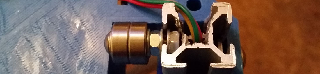
After further fighting to get the extrusion into the top frame I can turn my attention to the idler bearings at the top. RichRap's design called for bearings and a penny washer - but gcolburn's kit didn't contain these. In the end after a bit of head scratching I find a note on the facebook photos which mentions that the normal M3 washers could be used here - so once I established that, the idlers shown below went together and clamped on smoothly.
So far the printed parts have been quite substantial - but now I have to screw some bolts into a more fragile looking part - the carriage which connects the bearings on the columns to the pushrods, as well as the effector which holds the printhead. gcolburn suggested twirling one of the hex keys inside the parts before I tried to screw in the M3 bolts - this worked really well and I didn't feel that I was putting any of the parts under too much tension doing this.
Here is the assembled effector with the bolts and the pushrods shown:

One part I like about the gcolborne kit is that the pushrods and rod ends are made from metal - I think this will greatly increase the life of the printer. I was concerned about the quality of 3d printed rod ends in the original design and thought I may break them during assembly - the use of metal parts removes that problem. Its fine saying if you break a printed part you can print out another one - but not if its part of your only incomplete printer.
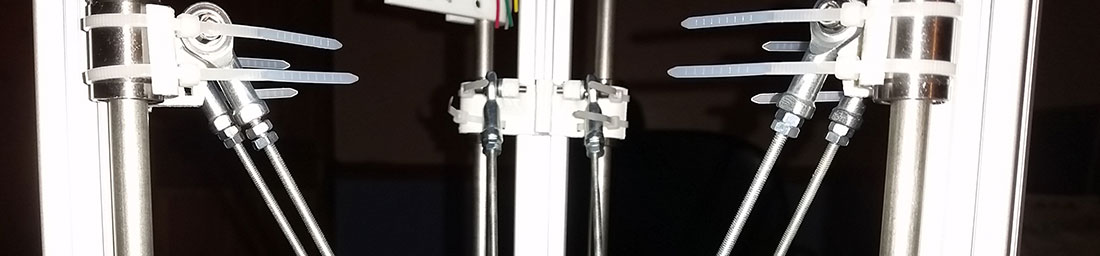
So now all that remained of the basic frame was to attach the print head carriage to the frame with cable ties around the linear bearings. This worked really well as the parts had channels built in for the cable ties to make sure they lined up well:
So here is a quick video of the effector assembly moving up and down manually on its columns.
Next - A fiddly bit!
Back to Part 2 Swirling metal and sore fingers
17-Apr-2015 Add comment
blog comments powered by Disqus Permanent Link