Building a RichRap 3dr - Part 1
My first journey into 3D printers
I've recently got my hands on a 3DR 3D printer kit so I wanted to use a couple of posts documenting its build. I plumped for the 3DR as I had been after a 3D printer for a while but was concerned about having space to use it. When I saw the design of the 3DR, which is within a tall cylinder as opposed to the more traditional cube shape of the MakerBot I knew that this was the one that I had room for in the man cave.
I got a bit confused as to where to buy this from. The design is by Richard Horne (RichRap) and I thought he was selling them, but an eBay listing for it implied that it was made by gcolburn but then a different company seemed to sell it. I spoke to RichRap who let me know he designed them and gave me some tips about what Hot end (the bit that applies the hot plastic) to choose, and then in the end bought the kit from SemiUtilitronic industries (aka gcolburn on eBay) via emakershop as it was cheaper than through eBay that way.
The printer kit arrived in less than a week - much quicker than I was expecting and it was quite a thing to unpack it - many many parts. I did wonder if I had don't the right thing when I was unpacking it as at that point I thought I had paid a lot for what I was unpacking.
Here is what I got:
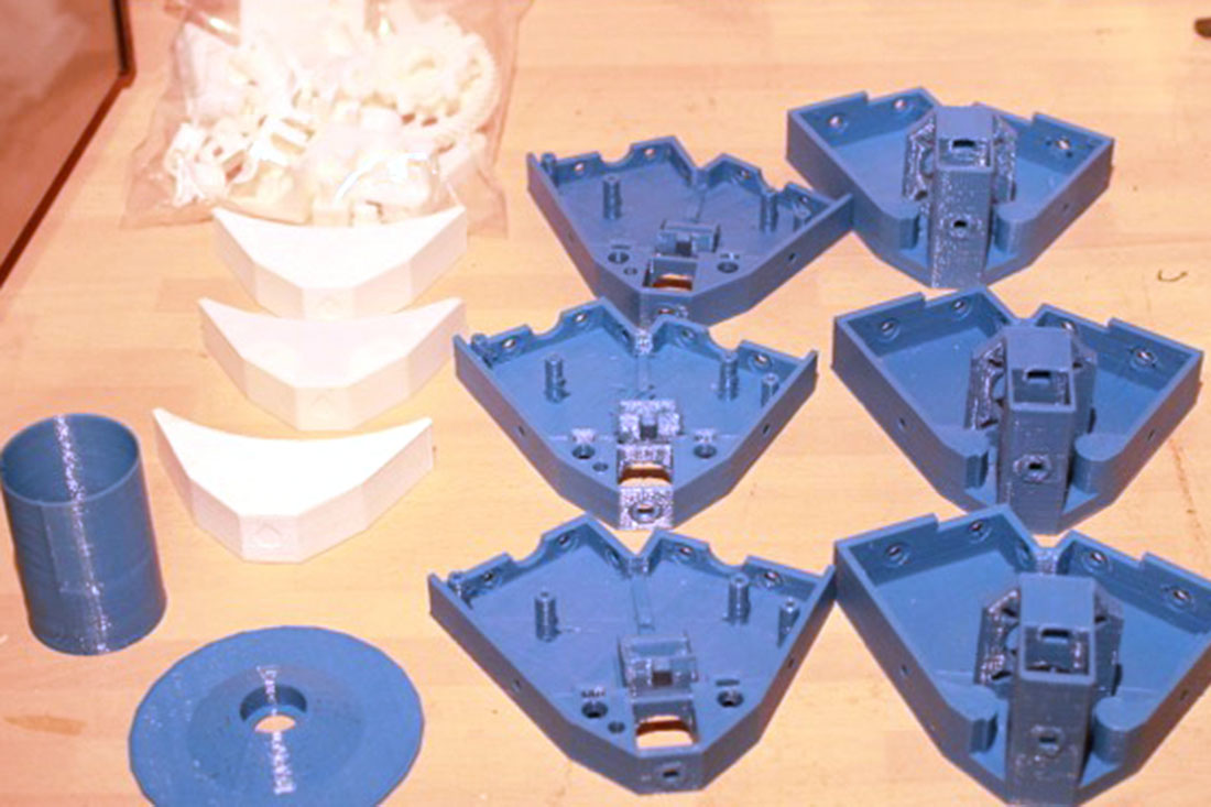 set of printed parts
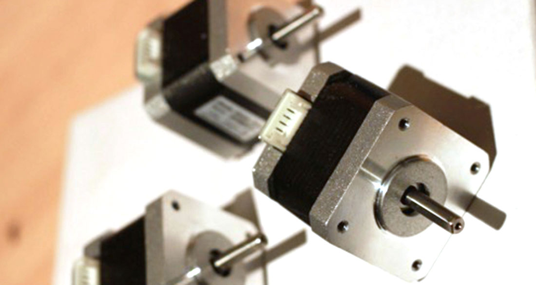 the stepper motors
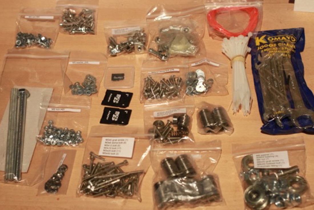 the well labled hardware
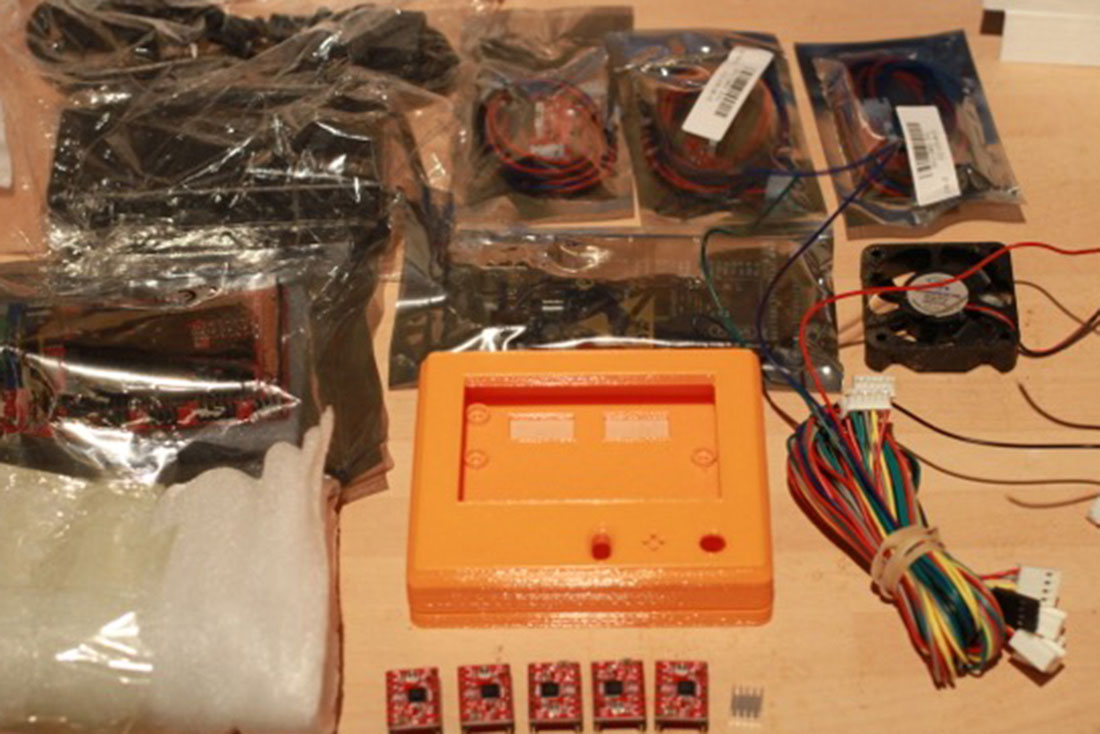 most of the electronics
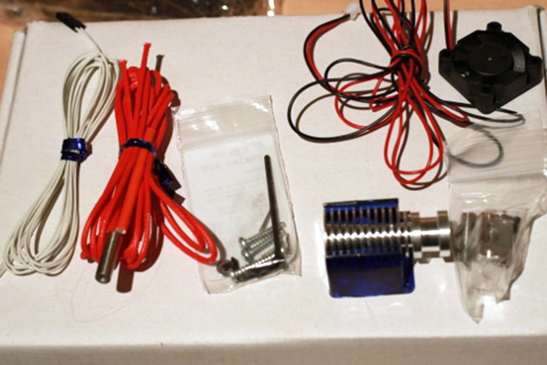 and the hot end
3D printers are described as machines that can replicate themselves - which I would deny! - but there were many printed parts in the box and it's been interesting looking through these and getting used to what sort of thing I might be able to make. Apart from one 3D trinket I was given, this is my first exposure to printed parts.
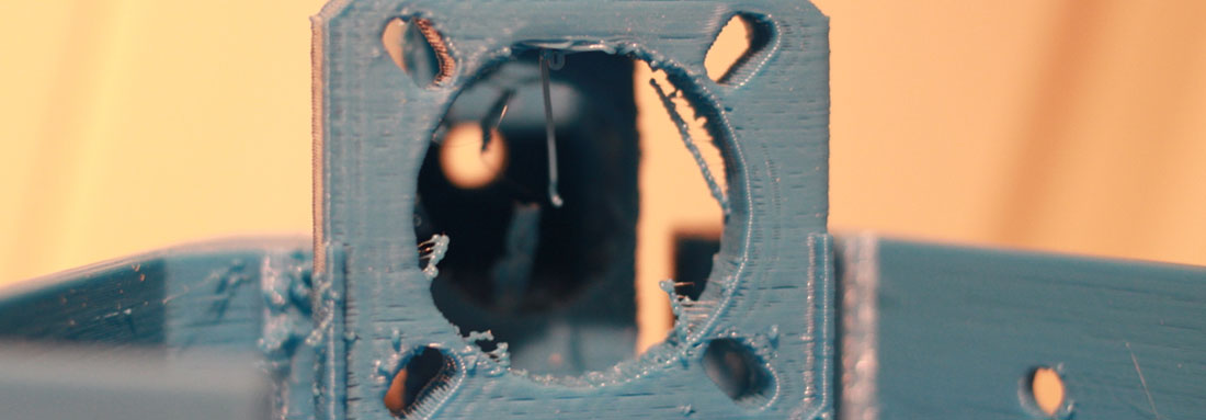
It's interesting looking at the quality of the printed parts - There are several parts which come in sets of three - and I can see the difference when I compare these. Of course they may have been printed on different machines, but I had read that you do need to clean up parts a little after creating then, as you do with injection molded plastic, so I spent a while using a nail file to sort out and remove the printed debris.
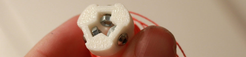
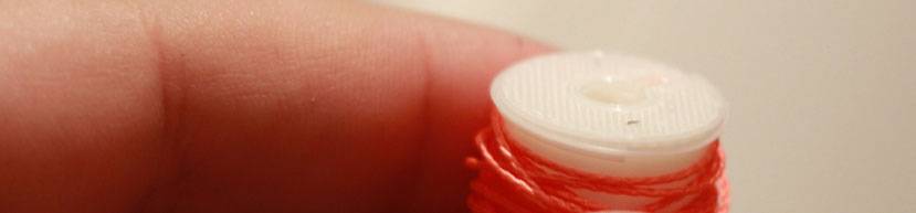
I know also that you have to be quite careful with the parts as they can sheer if stressed in certain way so I have been a bit over careful with the parts. The first issue I had was with the spools which fit on the stepper motor shafts. The spectra line wraps around these spools which then give drive to each of the carriage linkages. I was unsure of how much pressure I should use to push these spools on.

In the end I put the bolts into the plastic as you can see and pressed what I though way too hard to get it onto the spindle. In the end it felt a little like it ratcheted on to the motor and fitted really snugly even without tightening the bolts.
The next photo on the instructions showed winding the spectra line onto the spool - and I realised that I had to thread the line into some small channels inside the it - which I couldn't get to when it was on the motor.
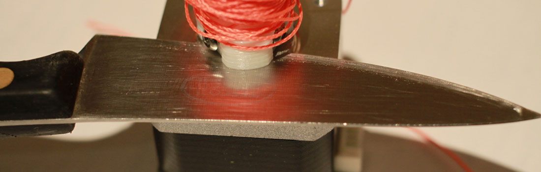
As I was trying to pull the spool off, the layers of the print at the edge started to come away - I was expecting I would have to phone them up and buy some spare parts.
In the end I put a kitchen knife between the spool and the motor which enabled me to push the spool off instead of pulling it - so I got away with it.
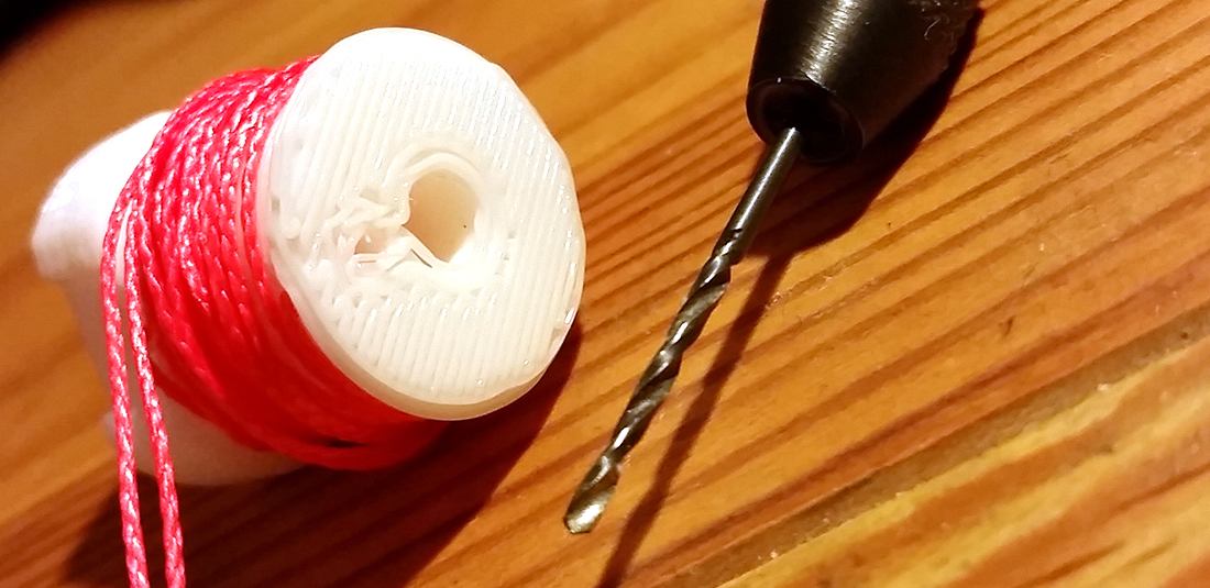
Getting the spectra line through the spools was also a nightmare. It took me a while to understand what I was meant to do with the spectra line - it almost doubles back on itself to make it pop out at the right point on the spool, and this was really confusing before I worked it out. Here is how it is threaded:

The spectra line separates at the end which makes pushing it through the channels problematic. I spent a while melting the end of the spectra line with a flame to fuse the spectra line strands together, but each time the plastic balled up at the end which didn't help at all. Finally I was able to make the spectra line end into a melted point which helped. I also felt a bit fat fingered trying to get the spectra line through - so if you are building one I recommend using tweezers to grab the end of the spectra line so you can see what you are doing. Finally I used a small drill and a drill vice to smooth out the inside of the channels - once I'd sussed that it got much easier. The whole process of getting these spools and spectra line attached took be about 2 hours - way longer than I expected.
In my next post I'll explain more about the frame and the hardware.
Part 2: Swirling metal and sore fingers
23-Mar-2015 Add comment
blog comments powered by Disqus Permanent Link